
(Updated to reflect new EASA regulations in force from August 2022.)
When a 2D instrument approach procedure (a procedure without glidepath guidance, previously known as a “non-precision” approach or NPA) is flown using the recommended Continuous Descent Final Approach (CDFA) technique a decision altitude/height (DA/H) is used. Just as with 3D approaches the pilot decides at this altitude/height whether to continue with a landing or go around. This is in contrast to the traditional “dive and drive” technique where the aircraft descends rapidly to a minimum descent altitude/height (MDA/H) and remains level at that altitude until visual contact with the runway environment or the missed approach point (MAPt) is reached.
The MDA/H is basically determined by the obstacle clearance altitude/height (OCA/H) of the procedure. The question of how to determine the DA/H for a CDFA has led to some debate. A 2D procedure is designed with the “dive and drive” technique in mind so that the aircraft never descends below the MDA/H. When a DA/H is used, then the aircraft will necessarily briefly descend below the DA/H even if a decision is made to go around as the transition from descent to climb can’t be made instantaneously.
Some people – and aviation authorities – have argued that as the design of a 2D procedure assumes that the aircraft doesn’t descend below the MDA/H, the DA/H used with a CDFA approach can’t simply be set equal to the MDA/H. Instead, a derived decision altitude/height (DDA/H) should be determined by adding a margin (e.g.. 50 ft) to the MDA/H to ensure that the aircraft never gets below the MDA/H on a go-around.
Other have argued that the “dip” below the MDA/H is negligible so that the DA/H can be set equal to the MDA/H. It is notable that Jeppesen generally depicts the CDFA technique on approach charts and then always computes the DA/H in the same way as the MDA/H without any add-on.
The question then is: Are there any regulatory or safety issues with using the MDA/H as the DA/H?
The relevant regulation is NCO.OP.111(a):
The decision height (DH) to be used for a 3D approach operation or a 2D approach operation flown with the continuous descent final approach (CDFA) technique shall not be lower than the highest of:
- the obstacle clearance height (OCH) for the category of aircraft;
- the published approach procedure DH or minimum descent height (MDH), where applicable;
- the system minimum specified in Table 1;
- the minimum DH specified in the AFM or equivalent document, if stated.
This description of how to determine the DA/H will give the same values as that of the MDA/H – there is no mention of any add-on. In fact, the GM (Guidance Material) to NCO.OP.111(a) states:
An aircraft may descend briefly below the DH on an NPA flown using the CDFA technique, in the same way as it may on a PA or APV.
Clear enough. Additionally, part-CAT and part-NCC (the ops rules for commercial operations and non-commercial operations with complex aircraft) include a GM (GM5 to CAT.OP.MPA.110 and GM7 to NCC.OP.110) with additional useful information:
The safety of the use of MDH as DH in CDFA operations has been verified by at least two independent analyses concluding that a CDFA using MDH as DH without any add-on is safer than the traditional step-down and level flight NPA operation. A comparison was made between the safety level of using MDH as DH without an add-on with the well-established safety level resulting from the ILS collision risk model (CRM). The NPA used was the most demanding, i.e. most tightly designed NPA, which offers the least additional margins. It should be noted that the design limits of the ILS approach design, e.g. the maximum glide path (GP) angle of 3,5 degrees, must be observed for the CDFA in order to keep the validity of the comparison.
There is a wealth of operational experience in Europe confirming the above-mentioned analytical assessments. It cannot be expected that each operator is able to conduct similar safety assessments, and this is not necessary. The safety assessments already performed take into account the most demanding circumstances at hand, like the most tightly designed NPA procedures and other ‘worst-case scenarios’. The assessments naturally focus on cases where the controlling obstacle is located in the missed approach area.
It is not difficult to make your own simple analysis to confirm what EASA writes. Let’s look at what happens when a 2D procedure (e.g. an LNAV procedure) is flown with the CDFA technique taking the MDA/H as DA/H and a decision is made to go around at the DA/H. (The procedure design figures I use are taken from ICAO doc. 8168 (PANS-OPS) 6th ed. Volume II.)
In the construction of a 3D approach (ILS, PAR, LNAV/VNAV or LPV) for an approach category A aircraft, the “dip” is assumed to be at most 42 ft. The basic minimum obstacle clearance (MOC) for the 3D approach is taken to be equal to this “dip margin” plus an 88 ft altimeter error, i.e. 130 ft. The MOC of a 2D approach is never less than 246 feet. There is no reason why the “dip” should be larger using the CDFA technique so it is clear that the risk of hitting an obstacle during the “dip” of a CFDA is considerably less than during a 3D approach!
On the other hand there could be a risk of hitting obstacles in the missed approach area if the aircraft is still below the DA/H at the point where an aircraft using the “dive and drive” technique is assumed to have started to climb. (Indeed that’s the point made by the quote from part-CAT/NCC above.) I’ll show that this is very unlikely.
The following diagram shows the worst case CDFA and missed approach vertical flight path for a typical 2D approach. (MAPt at threshold, threshold crossing height 50 ft, nominal glidepath angle 3°, DH the lowest possible for a 2D approach – 250 ft.)
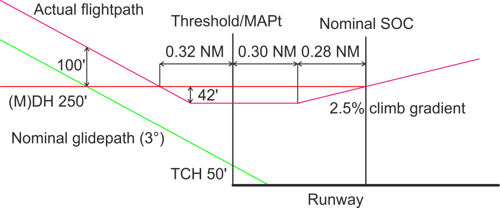
Pilots are expected to keep within ±100 ft of the nominal glidepath during a CDFA approach so the latest go-around will happen if the actual glidepath is 100 ft above the nominal glidepath. This go-around point will be 0.32 NM before the MAPt.
The start of climb (SOC) point assumed by the procedure design is at a distance past the MAPt determined by the MAPt fix tolerance, pilot reaction time (3 s.) and “transitional distance” (15 s. flight) at the highest permitted final approach speed and a 10 kt tailwind. The highest permitted final approach speed being 100 kt IAS, assuming (as in PANS-OPS) an airport elevation of 200o feet and OAT of ISA+15 the maximum TAS will be 106 kt and with the 10 kt tailwind the maximum ground speed will be 116 kt. Assume the tightest possible (zero) fix tolerance as this will give the shortest distance to the SOC. The SOC will then be located 0.58 NM beyond the MAPt. In order to reach the DA/H from the “dip” altitude of DA-42 feet by the SOC given the minimum 2.5% climb gradient expected during a missed approach, the climb must start at the latest 0.28 NM before the SOC or 0.30 NM beyond the MAPt. (The 88 feet altimeter error margin applies equally to the missed approach so we don’t have to take it into consideration.)
In all the aircraft can travel a distance of at most 0.32+0.30=0.62 NM after the decision to go around before it has to be established in the climb. At a GS of 116 kt, this is 19 seconds. Even considering pilot reaction time, this is clearly much longer than it will actually take to make an approach category A aircraft start climbing. Thus we can conclude that there is a large safety margin even with no addition to the DA/H over the MDA/H.